HOWTO: The!Cart CPLD logic update via JTAG
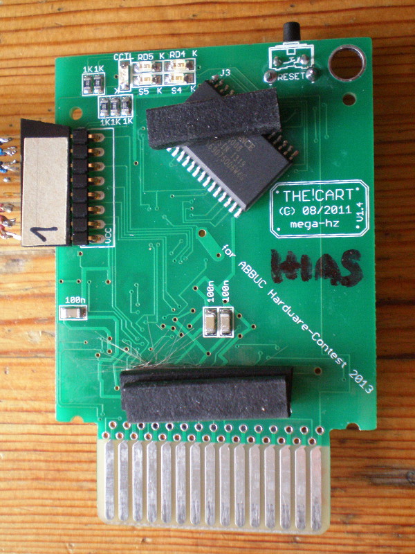
Open the cart shell, the top layer of the PCB looks like this:

Note that the LEDs are on the front. The JTAG connector is located
in the top left
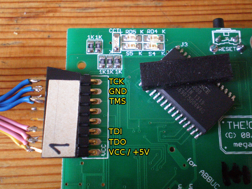
Here's a detailled picture of the JTAG connector, with pin assignment:

Note: there are 8 unpopulated holes for the JTAG connection,
unfortunately they are located too near to the edge of the PCB - if you
solder in a standard (either 90 degrees or straight) header connector the
PCB won't fit into the cart shell. It's best to use a stick a standard
2.54mm 8-pin header through the holes and hold it in place at a slight
angle so that the pins make contact.
Step-by-step update instructions
- Plug the PCB into the cart slot with the LEDs facing towards you
(in case of XL or XEGS) or upwards (in case of XE). Also be sure
to insulate the PCB so that the metal door of the XL cart slot can't
touch the PCB - otherwise you'll have a short circuit and both your
Atari and The!Cart could be damaged.
- Connect your JTAG cable.
- Power on the Atari.
- Use your JTAG programmer software to update the Xilinx XC95144XL
CPLD with TheCart.jed. While doing that hold the JTAG header connector
at an angle to ensure you have a good connection.
- Alternative update method: program TheCart.svf using an SVF
capable programmer, for example UrJTAG.
- Power off the Atari and remove the JTAG cable.
- Power the Atari on again to verify that everything works fine.
- Unplug The!Cart and reassemble the cartridge shell.